XS 650 False Oil Tank
Posted on 12th Oct 2014
XS 650 oil tank electrical box
By bungking
How to Make an Electrical Box for a XS650 from www.bungking.com


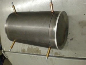
Building a custom XS650 or similar custom bobber/chopper using a motor from Japan? Most of these motors have an oiling system that is self contained or wet sump so they don’t have the external oil tank used by Harley Davidson, Triumph, or other similar style bikes. We are so used to seeing a tank in a location under the seat that most custom bikes look strange if they don’t have one. Here we made an oil tank looking box to contain all of the electronics on our XS650 project. This is a step by step guide to making your own or some ideas about how to go about it.We knew we wanted to have a round tank, so we started with som 6″ dia mild steel tubing for the shell. We wanted to have endcaps that were dished inward to match what we had going on the gas tank. We first cut out some 7″ circles from 16ga mild steel on our pullmax with the circle cutting jig. We then set up our pullmax with some doming dies and hammered on the endcaps until the desired shape was achieved. You can find the 6″ of 5″ tubing cut to your desired length and a variety of weld on endcaps at our online store, here is a link to our oil tank page http://www.bungking.com/tanks/oil-tanks.html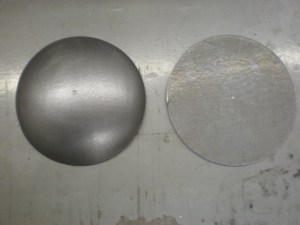
We next trimmed the domed endcaps to size to fit flush with the outer diameter of the tubing.
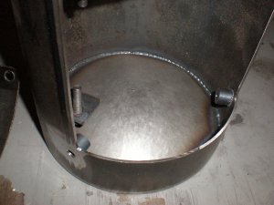
We needed to fit a coil, voltage regulator, starter selenoid and ignition module all inside the shell. To start we mounted the coil with some 1/4×20 threaded bungs that we welded to the inner shell.
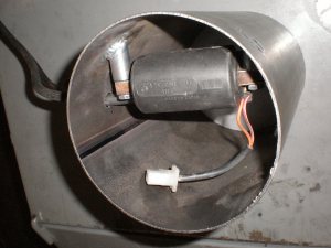
Once we knew the location of the coil we drilled two holes in the tank shell to allow a clean exit for the spark plug wires. 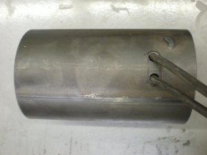
Next we wanted to mount the ignition module and the voltage regulator. We made a sheetmetal partition to go in the center of the tank shell. We welded a set of studs to the sheetmetal partition on either side, spaced correctly to mount the ignition module and voltage regulator.
We then welded the partion into place in the center of the tank shell allowing room around all the components for enough air flow around them to keep them cool. We then made a small tab with a stud to mount the starter selenoid.
Now that all the electrical components are in place and the mounting tabs fully welded, it was time to install the endcaps, so tacked the endcaps in place.
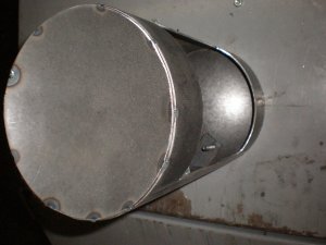
After we were happy with the fit we fully welded the tank encaps to the shell and ground down all the welds and finished all edges with a DA sander.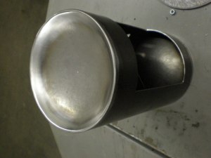
We then cut another section of 6″ tubing and made a cover for the access hole in top of the box. We started by predrilling the cover in the corners for a location to bolt it down to.
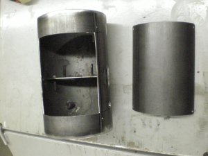
We then set the cover on the shell and drilled the same 1/8″ pilot holes in the shell. We use some clecos to hold things in place while drilling.
We next drilled 1/2″ holes in the tank shell and welded in some 1/4″ x 20 threaded bung inserts in all four cornes to hold down the cover.
Shows the cover over the access hole bolted in place.

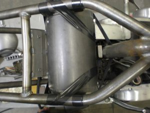
With the box all made up now, it was time to mount it to the chassis. To hold the box away from the chassis we placed some steel stock between the tubes and the box. This will give us a gap after everything is mounted a min of 1/4″ of space is desired to keep parts from rubbing together when everything is vibrating going down the road. My favorite method of holding items in place for mounting is with elecrtical tape. It is stretchy enough to allow adjustment and still holds parts firmly in place.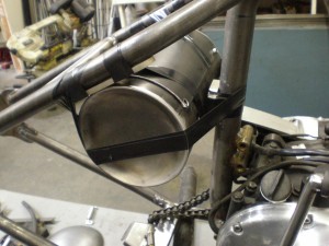 Once everything is in place, we made up a rear and front mount for the electrical box.
To find a bunch of the parts we used for this build please visitwww.bungking.com
 Loading... Please wait...


